Impressions from the International UV Filter Radiometer Comparison, 2017
The campaign started successfully before the scheduled start. Most radiometers arrived at Davos in time.
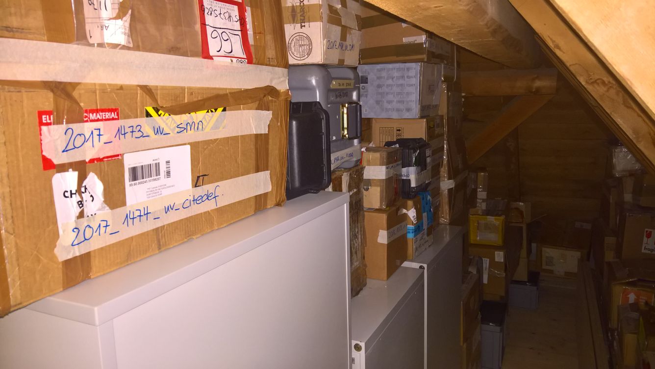
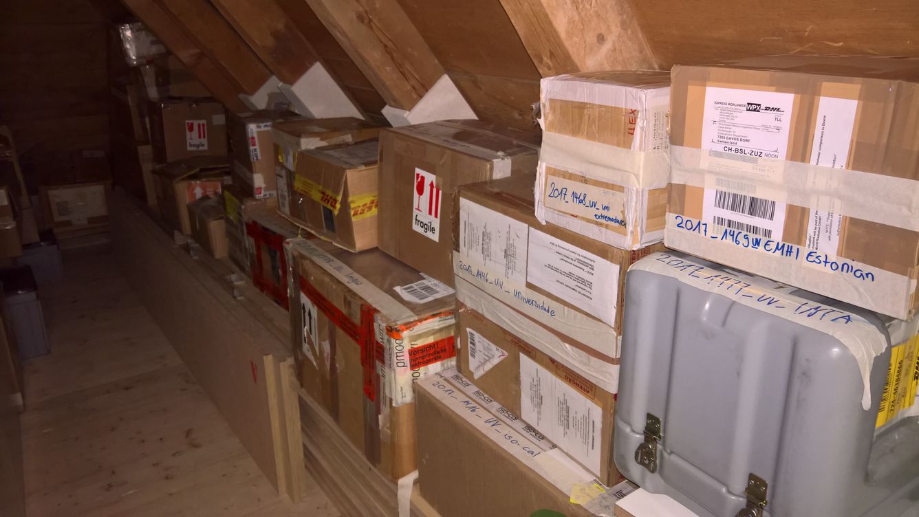
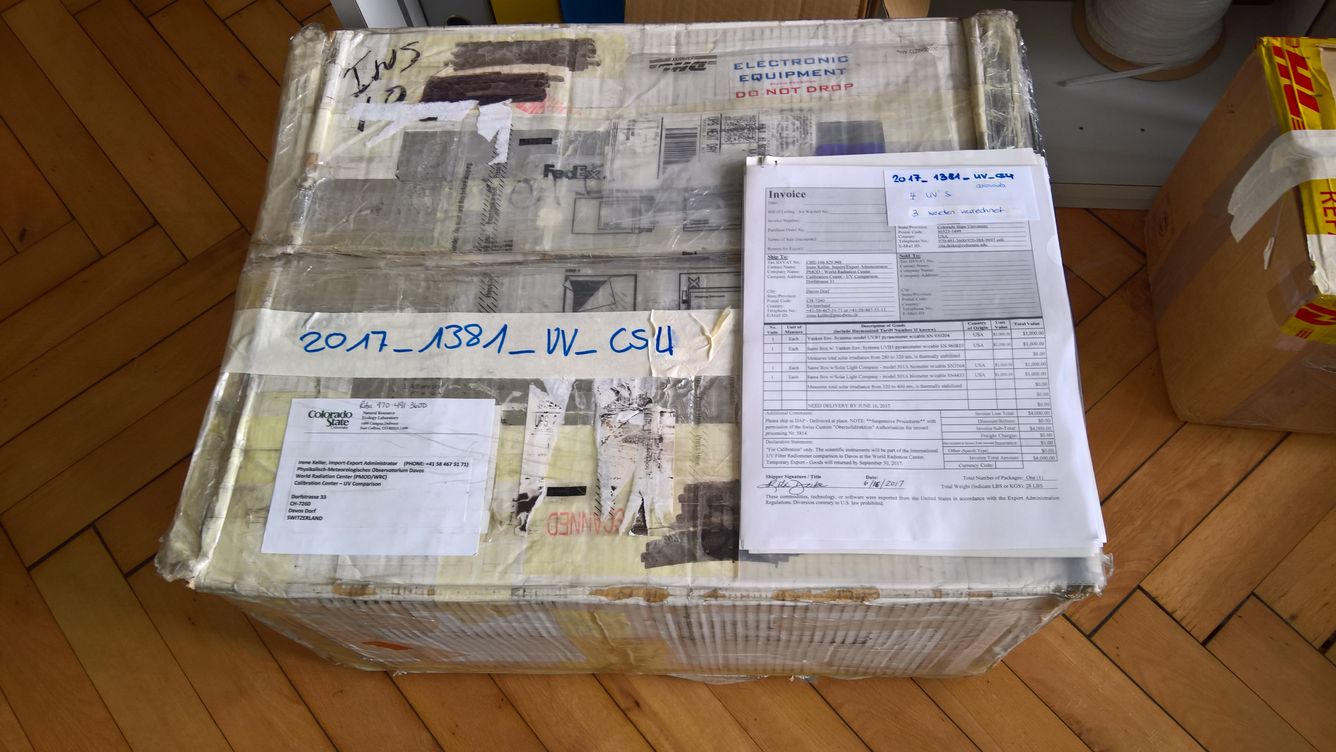
Shipping
Around 70 Radiometers participate at the campaign. Thanks to the shipping departement for the registration of the boxes and our civilian servant for the help of unpacking all the boxes.
Calibration Procedure
Absolut Calibration
-
Reference Spectroradiometers
The absolute calibration factor of broadband radiometers is determined relative to either the reference spectroradiometer QASUME or QASUMEII.
Picture of the QASUME and QASUMEII reference spectroradiometers during the campaing. The temperatur controlled boxes with the Bentham DM150 double spectroradiometers are located below the roof platform. The entrance optics are placed on the roof platform and connected to the spectroradiometer via fiber cables. -
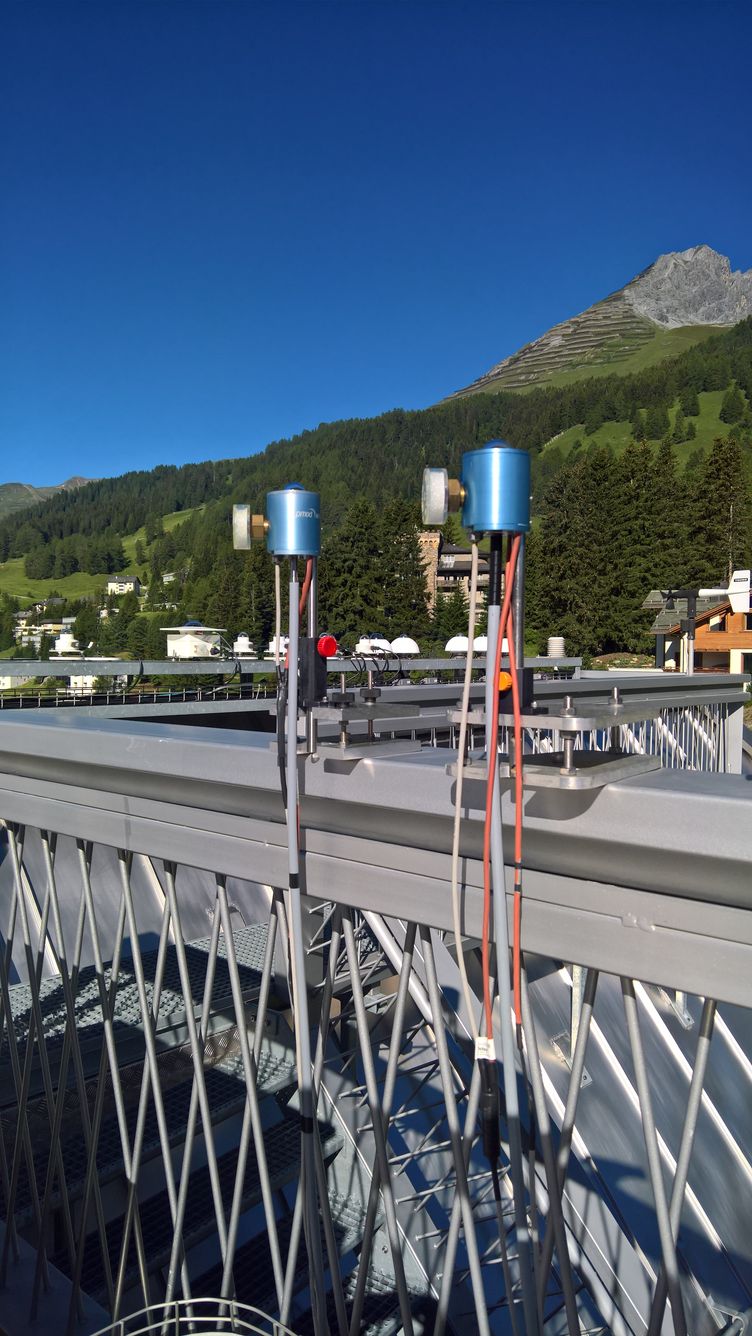
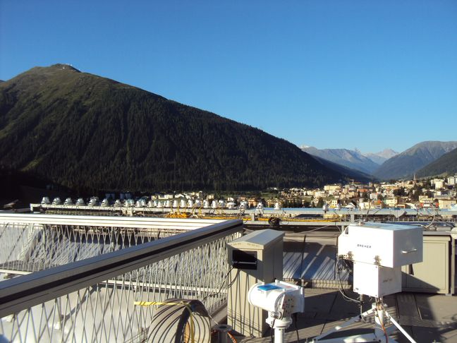
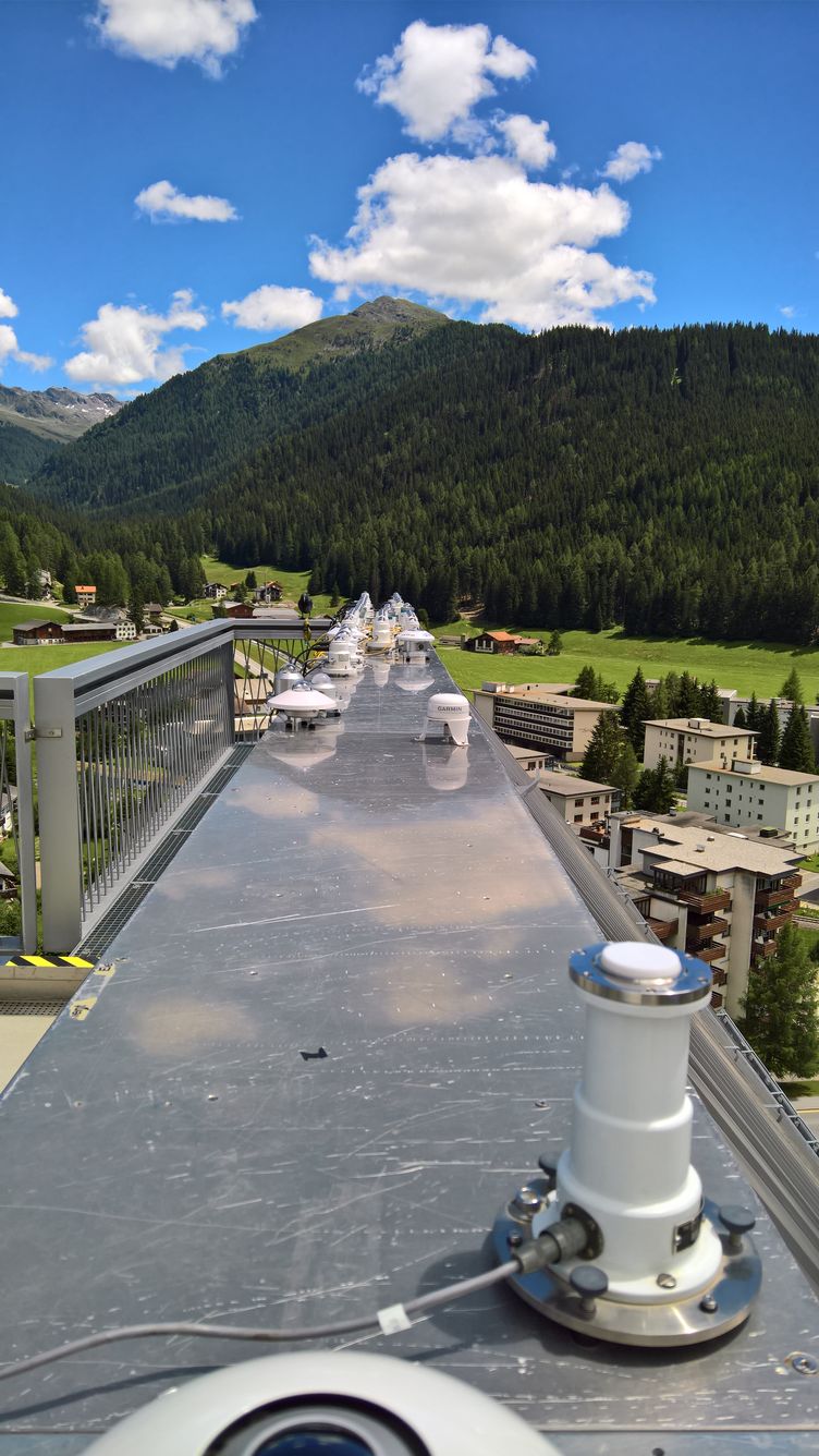
Roof Platform of PMOD/WRC
For the absolute calibration synchronized measurements from the radiometers and the reference spectroradiometer are acquired using the sun as light source.
Picture of the outdoor roof platform of PMOD/WRC. The first set of Broadband radiometers are mounted on the long bench. 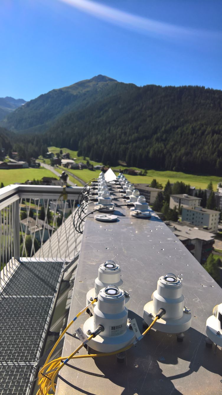
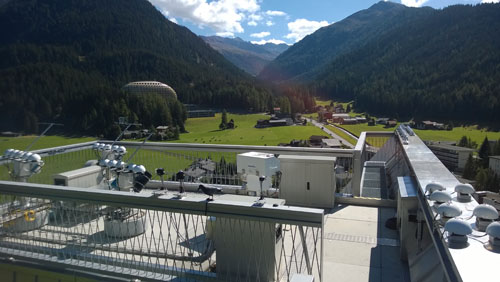
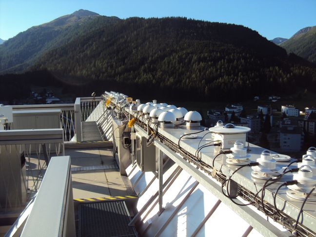
Picture of the outdoor roof platform of PMOD/WRC looking towards the east. 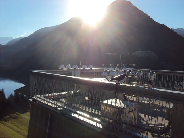
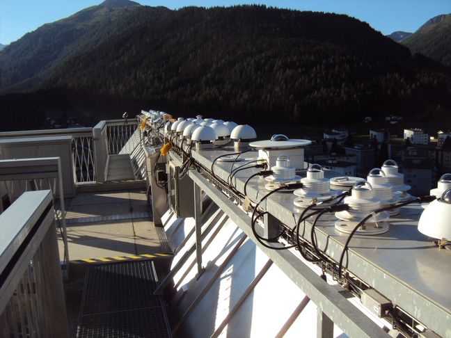
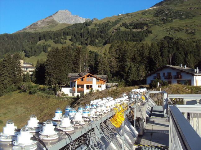
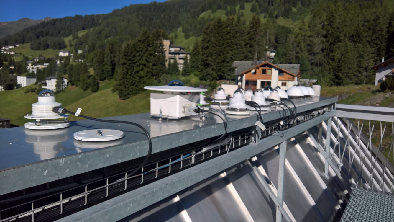
More picture of the outdoor roof platform of PMOD/WRC. 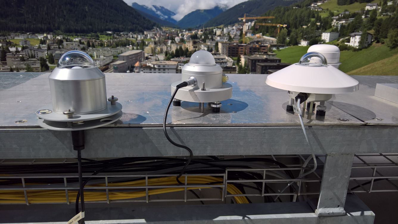
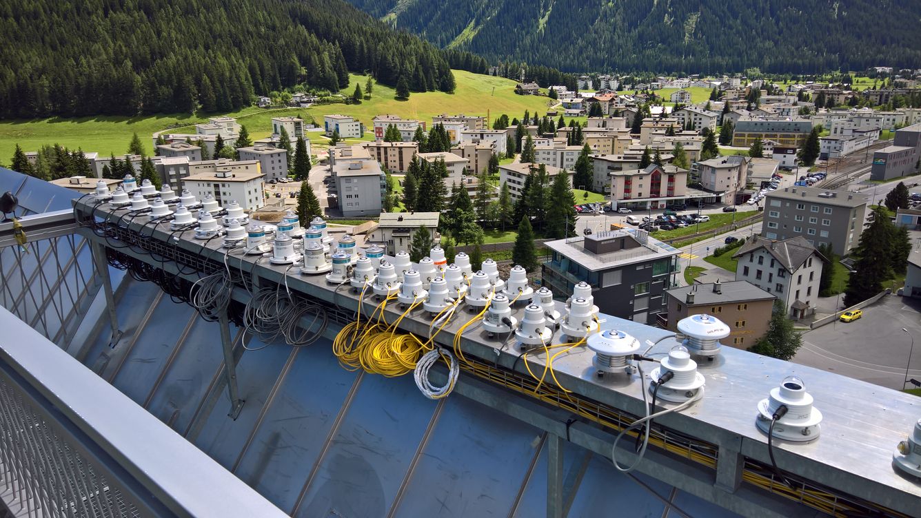
More picture of the outdoor roof platform of PMOD/WRC. 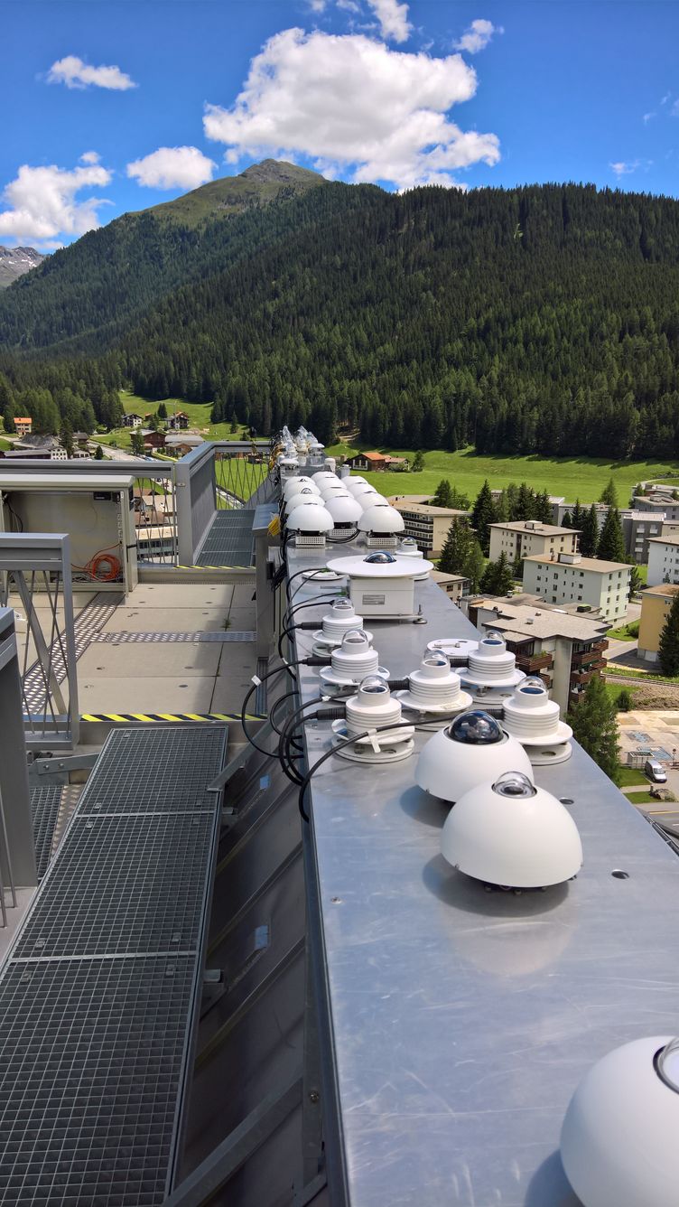
More picture of the outdoor roof platform of PMOD/WRC. 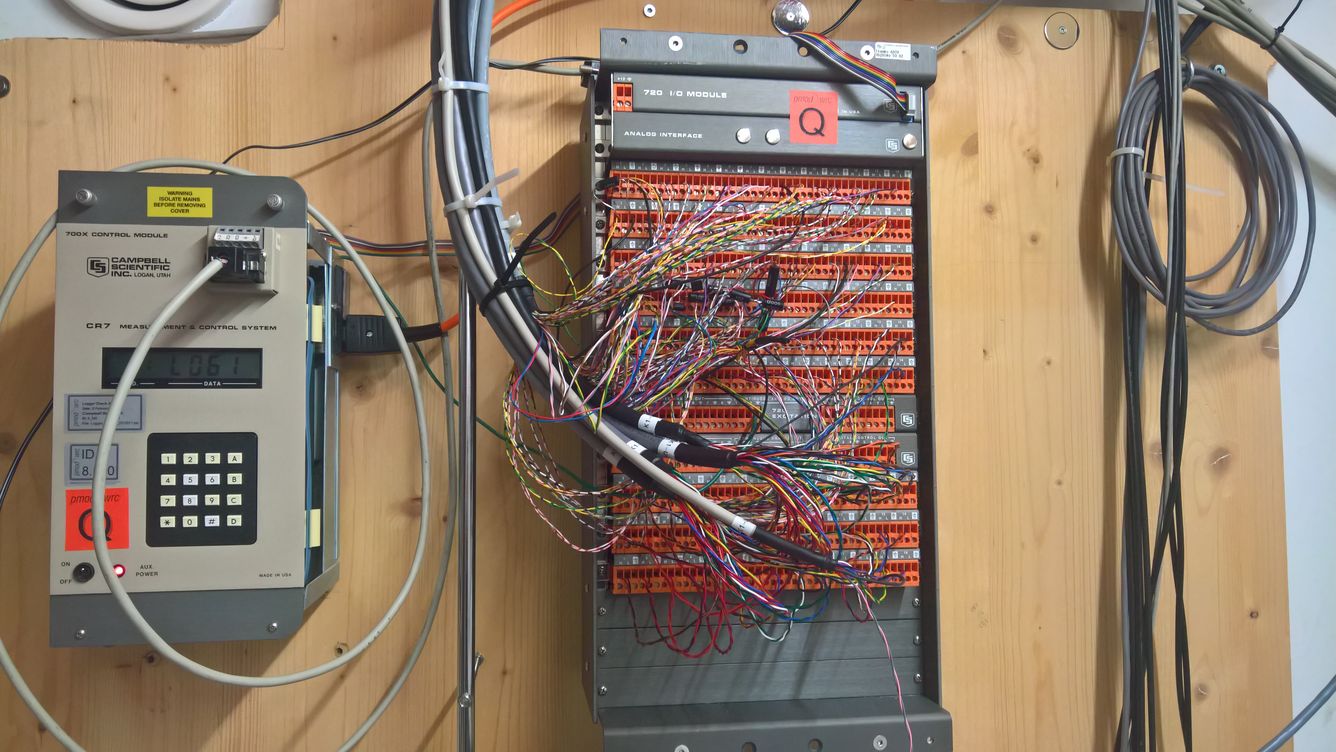
The data acquisition logger: A Campbell CR7. 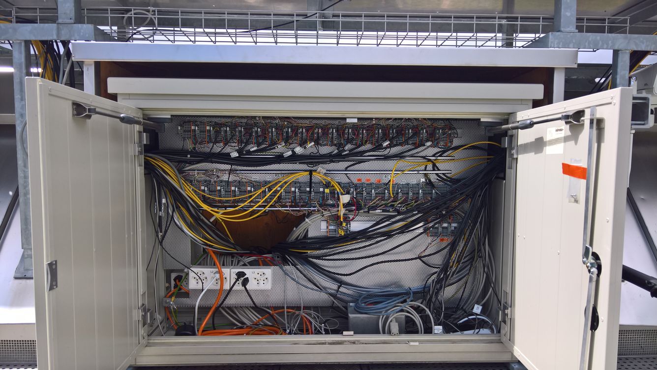
The 1st intermediate connection panel located on the roof platform - for the cables running from the radiometers to the CR7 logger. 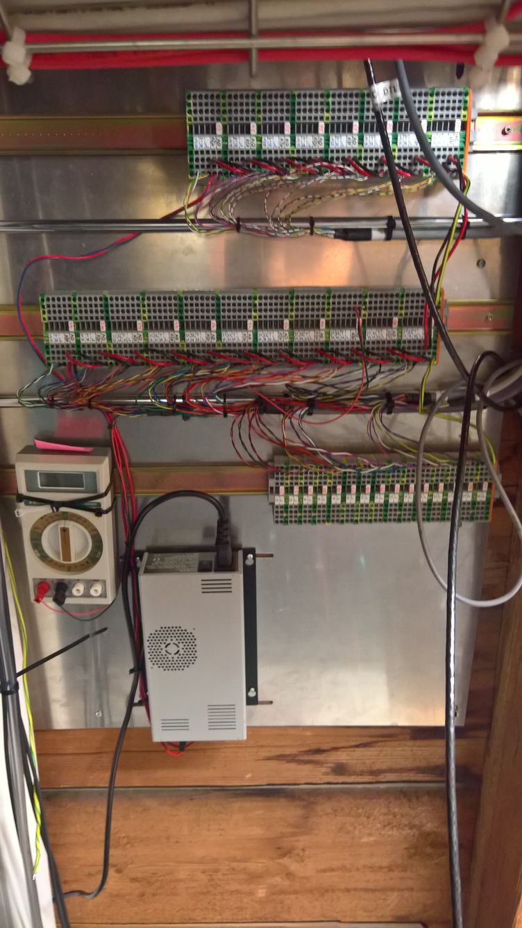
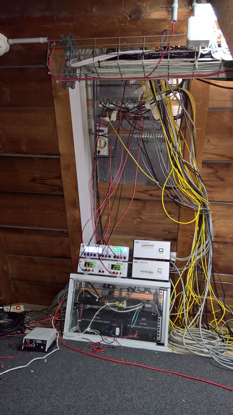
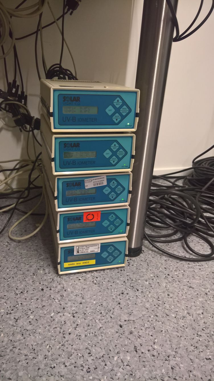
The 2nd intermediate connection panel located under the roof. Five 12 V DC power supplies are neccessary to supplied all radiometers with power. The Solar Lights 501 digital radiometers are controlled be the SL Recorders. 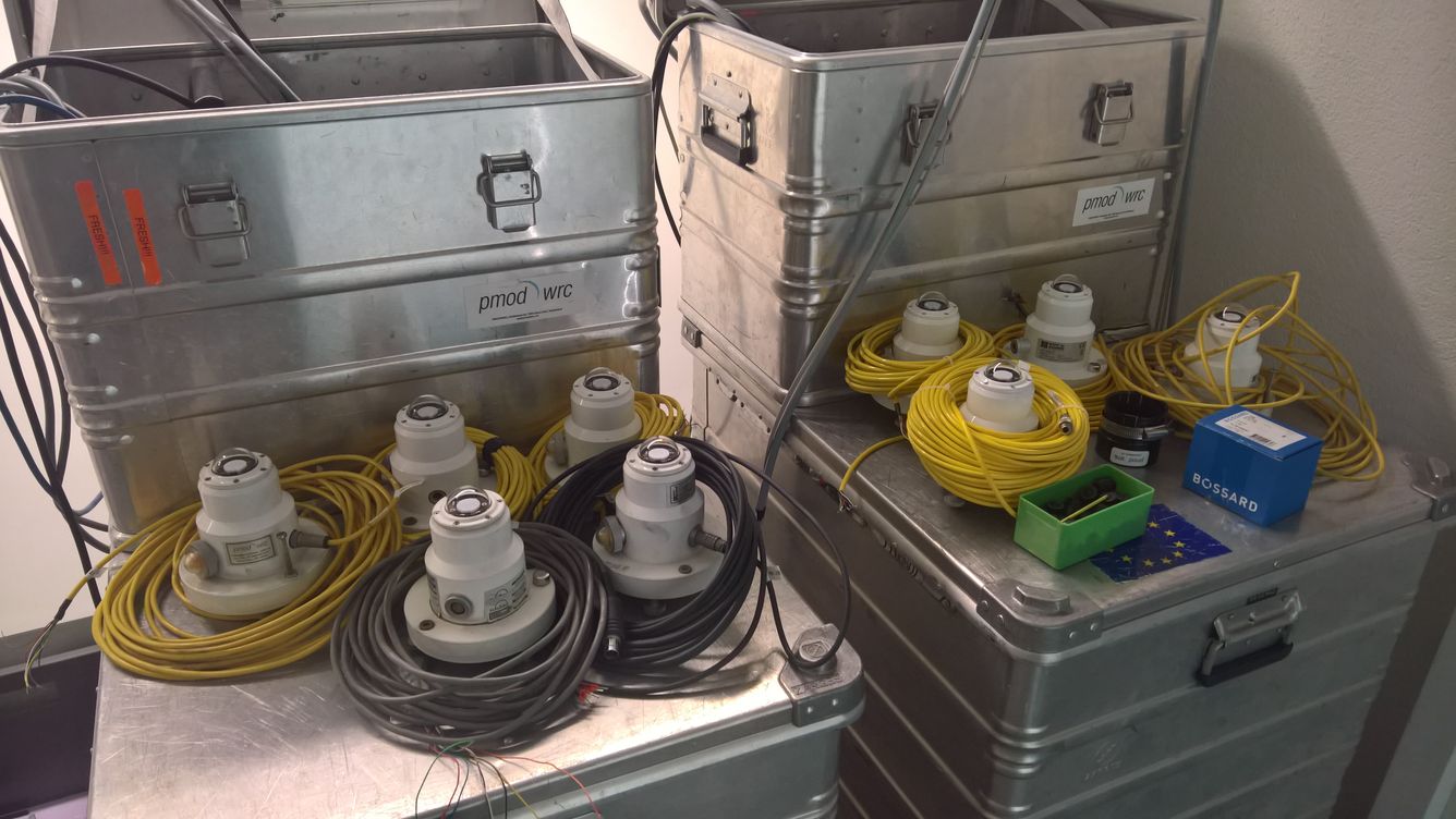
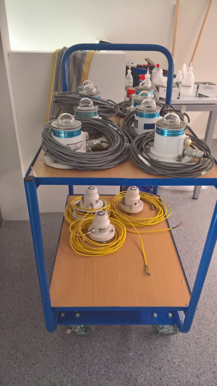
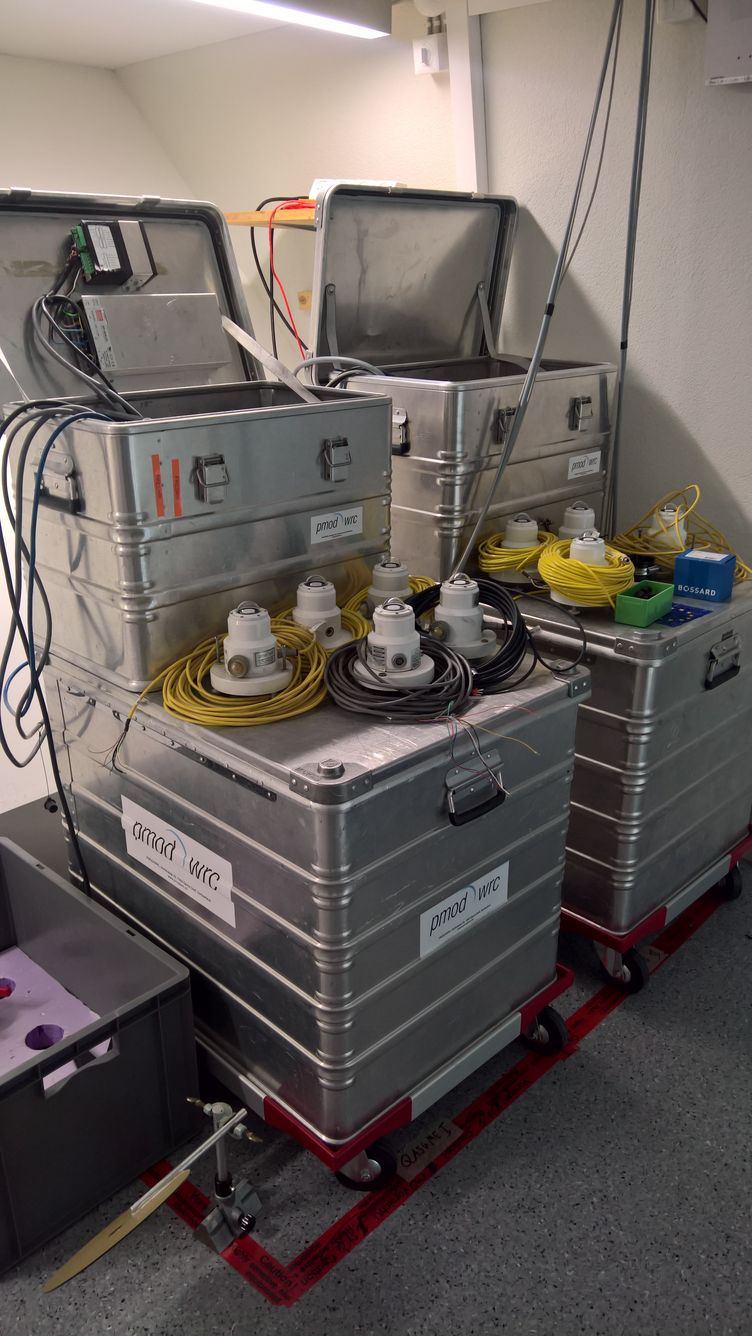
More radiometers waiting to be installed... -
Optical Laboratory - Dark room
After sufficient recording of sun irradiance the instruments are taken to the darkroom.
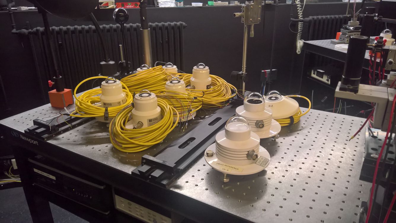
The first 10 radiometers are waiting for the instrument characterisation in the laboratory (SRF and ARF measurement). -
Spectral Responsivity Setup (SRF)
The optical table of the SRF setup is shown in the picture below. The light of a 1000 W Xenon lamp is focused to the entrance slit of an Acton SP2500 double monochromator. The UV broadband radiometer is illuminated by monochromatic light in the wavelength range from 270 to 420 nm. A Silicon diode monitors the stability of the system.
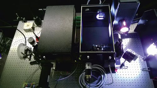
Picture of the SRF Setup showing the light source on the right, the open SP2500 monochromator and the test instrument on the left. -
Angular Responsivity Setup (ARF)
The measurement of the ARF is carried out on a 3 m long optical bench. The light source is again a 1000 W Xenon lamp. The collimated beam illuminates the radiometer mounted on a goniometer.

Picture of the ARF setup with the Xenon lamp on the left and the radiometer mounted on a goniometer on the right. In the center of the bench a baffle and bandbass filter is mounted.